
It might be argued that the previous post was all about the preparations for laying the track, but the cork sheet provided the road bed. It was now necessary to gather the plan and the materials together.
Templates
When printing “full size” templates (technically 1/64th of the prototype!) Templot can include reference lines, with an outside border. I removed these with a craft knife and a steel straight edge, and also took a small piece off each corner, leaving just a little bit of the references lines showing at these places. A grid to match these spacings was drawn on the cork, and the individual templates could be aligned over the grid for gluing down. As I progressed, I realised that two of the edges (one end, one side) could be trimmed back to just inside the line, to forestall any overlap from subsequent sheets. Everything was ready, so out with the PVA glue, a spreader and a small printing roller. Initially I used the roller to help spread the glue, but soon found this to be unnecessary and messy: but it was great for smoothing out the paper and getting it stuck down very flatly. The “secret” is to use fairly little glue, and to do only 3 or 4 sheets at a time before applying more adhesive to the surface. A steady, methodical routine will see surprisingly rapid progress.
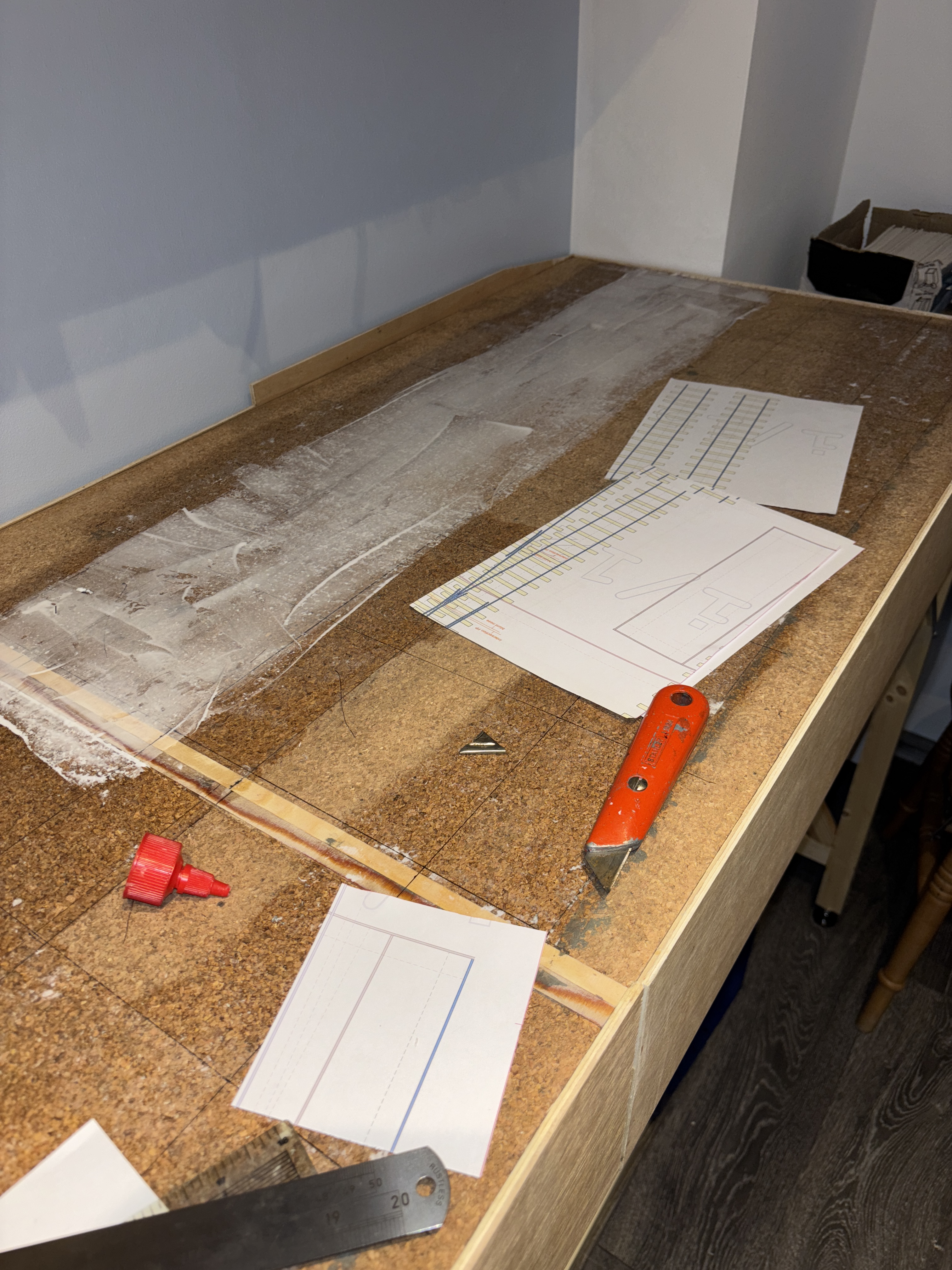
As you may notice, I did not worry too much about getting glue over the baseboard joint, but it is surprising how effective capillary action can be – and how strong a thin layer of PVA is, too!
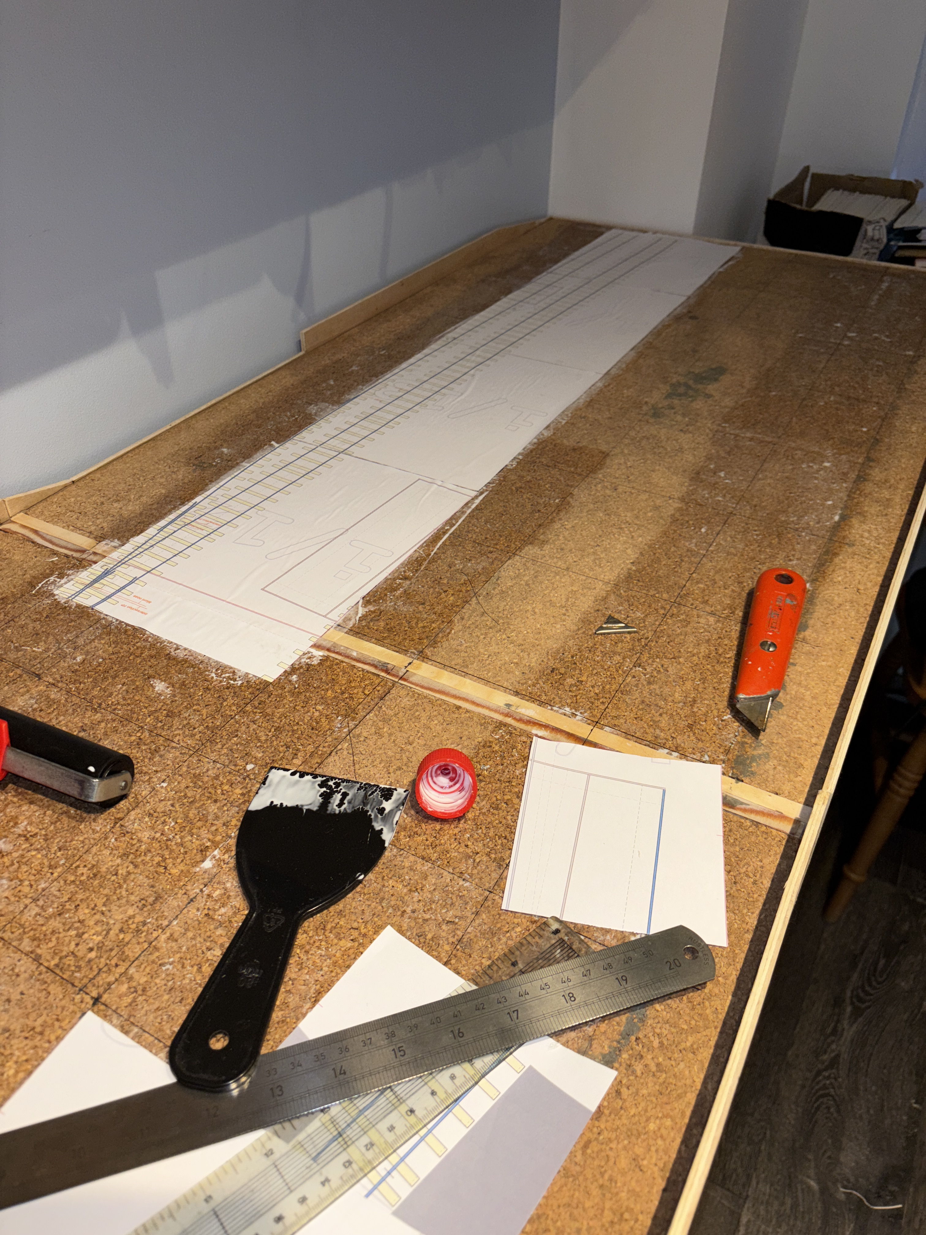
To forestall any questions, I did a bit of reading around various forums about how reliable the paper would be. There were lots of alarmist theories (e.g. “I would be worried about the paper delaminating”) but when it came down to it, very few comments from people who had actually done it – I found two, but one had used 1mm thick card and that’s not the same as what I was thinking of doing. And let’s be honest, it’s just normal printer paper, but it gets glue on one side at this stage, and will get glue on the other side when it comes to laying the sleepers, and when I get around to ballasting, diluted glue will be applied and will probably soak through the paper into the cork. If it all falls apart in 5 years, I will let you know…
…but. You may notice some darker areas of cork in the above photos. That’s where I had glued down some templates, only to not like the flow of things, so they all came up. After I had added all of the sleepers and switch timbers, too. After a soak with diluted white vinegar and a drop of washing up liquid (dish soap, if you are in North America!) it did come away, but without that soak, it didn’t come away easily – and that’s before the application of dry ballast and diluted glue, yet to come. I think I shall be safe from the worries reported by people who haven’t tried this out!
Sleepers
In between laying sections of paper and allowing for it to go off (you can get on with another section of templates once the first batch is down, but it starts to get messy and a bit boring!) I worked on creating the sleepers and point timbers, and filing rails for use as crossing vees and point blades.
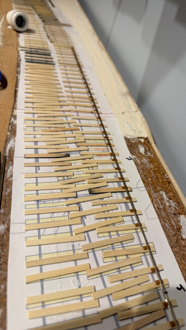
Making the timbers was easy: I bought some lime strips, 2mm x 4mm for sleepers and 2mmx5mm for switch timbers, set up a chopping tool, and cut away. You can produce several hundred an hour in this manner, whilst watching the box. Initially I used a NWSL “Chopper”, but I found that the clamp holding the set square in place started to creep slightly, and the sleepers started getting longer, so I changed over to a different one – a Proses TC-105, which I had bought online. This retained its settings, although I felt the base to be not quite as robust/rigid. It is more versatile, though.
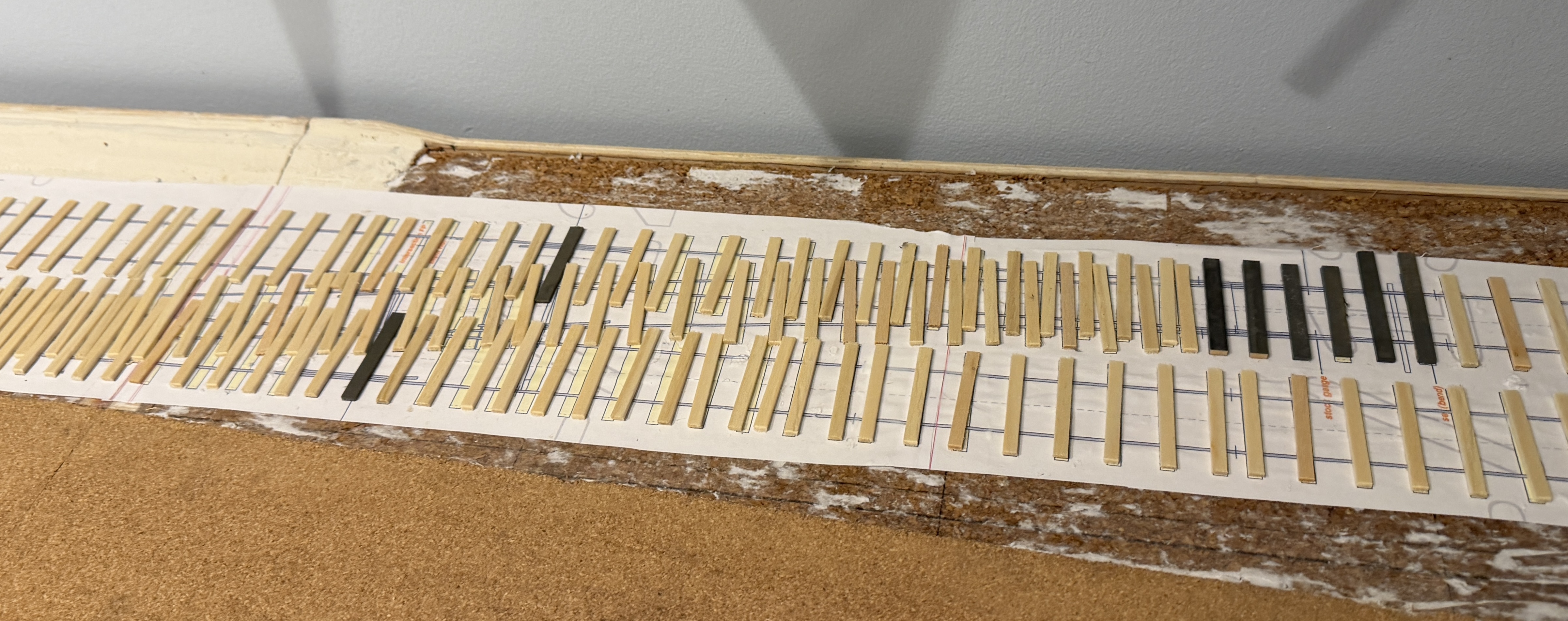
On a GER branch in my chosen era, they used wider timbers (12″ wide) under the switches and one under the crossing nose, but 10″ wide sleepers everywhere else, interlacing the sleepers for the main and curved routes – this is where an eye for detail when looking at period photos comes into its own. At some stage, on more important routes with heavier traffic, it appears that wider 12″ timbers started to appear under the crossings and associated check rails, laid “straight” to the main route, and after about 1915, replacement and new works started to be laid with full timbers for the whole turnout. The 12″ wide timbers for my use were of three lengths, 9′, 9’6″ and 10′ to account for the diverging route on the turnout. Plain track is laid with closer spacings at rail joints, with a mixture of 30′ for recently relaid line (the “main” line approaching and into the station) and 24′ rail lengths (elsewhere) spaced according to some information I managed to find by searching online and reading some books and magazine articles. I know that most people won’t care about this detail, and even fewer may notice, but ultimately, I am building this layout for me! After a few hours, you will have amassed a small pile of sleepers (make sure you put the timbers in a different pile) and can start sticking them down. I did stain a lot of them, then realised that after glueing them down, the Edmund Fitsander was going to be paying a visit, so maybe this was a waste as I would be doing it again, later on…
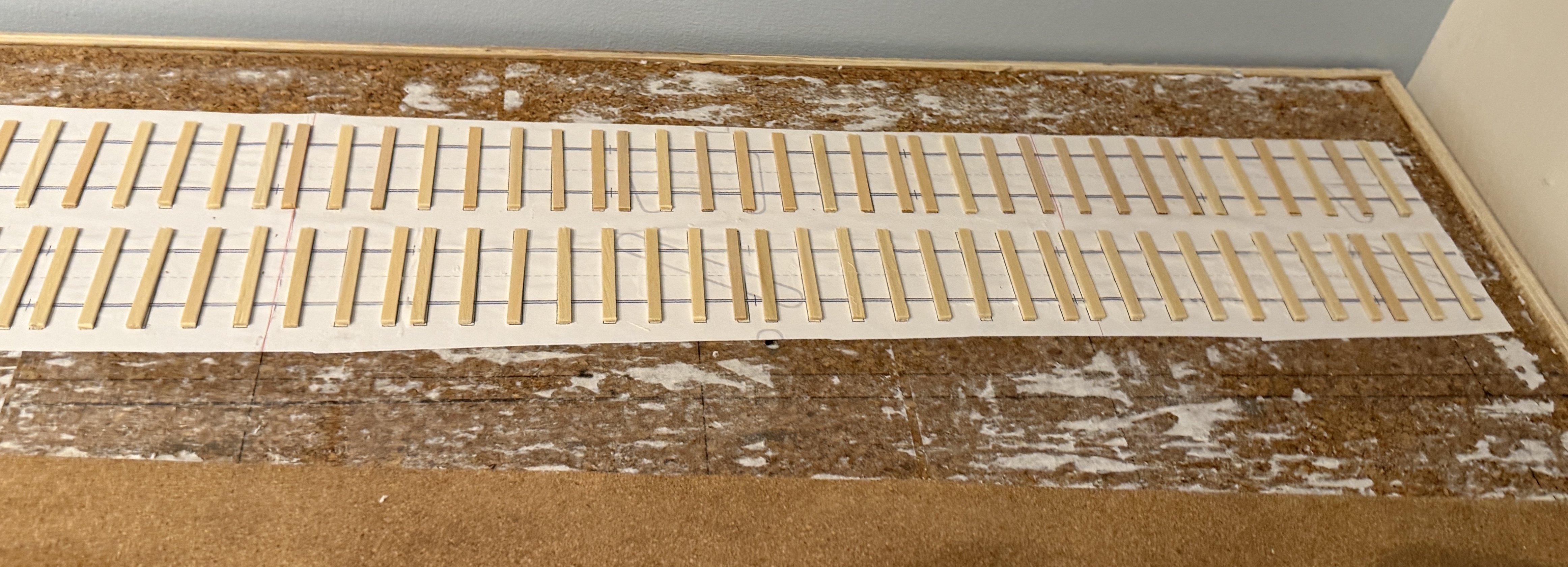
Obviously, a thin smear of glue was applied, sleepers put in place, and then some weights applied for an hour minimum.
Where turnouts were involved, I had already stained all of the timbers, which actually helped me remember where I was in the process. This also clearly marks where the crossing nose will be located.
Rails
I have the used the SSMRS code 87 bullhead rail, which is good for use on a pre-grouping layout – it is slightly lower than the later BS 95lb/yard rail, and actually covers a wide range of rail weights as the code 87 reflects the height of the rail: 0.087″. On the prototype, rail weight was often increased by rolling the rail with a thicker web, which is almost impossible to see on a layout. On my previous layout, I had used 4mm scale code 75 rail, which was fine but this time, 30 years later, I used the more accurate material because (1) I had become aware that the code 75 was rather narrow at the head of the rail – which is visible to the trained eyed, in proportion to the width of the wheels running on it, etc – and (2) the code 87 rail and chairs were not available 30 years ago!
I wanted to include fishplates, and decided that glueing pieces of etched brass or moulded plastic either side on the cosmetic joints would be a pain in the backside, so investigated if the new Peco code 75 bull head rail fishplates might be of use. They are, but they are (not surprisingly) a bit tight on the rail, but this was easily solved by inserting the blade of a suitably sized screwdriver into them, and sliding it along.
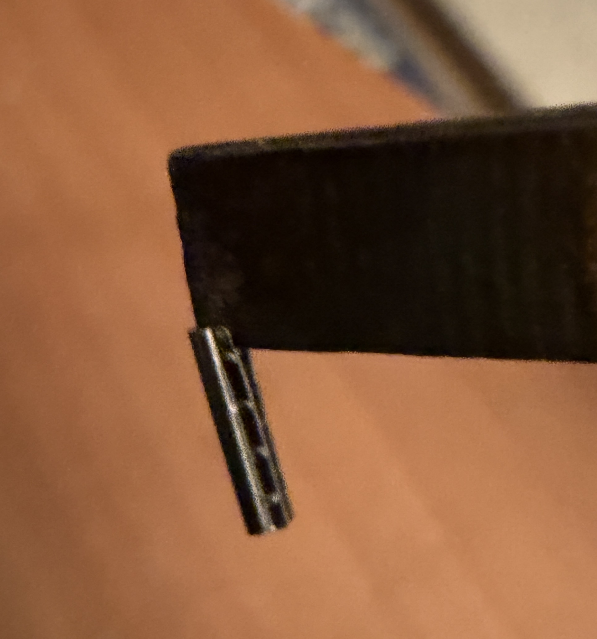
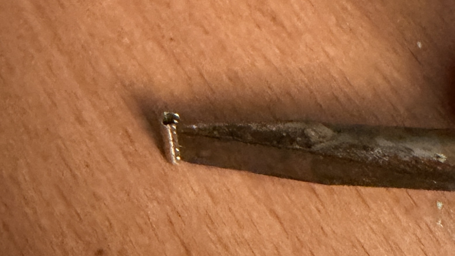
These are nice as they have the wrap-under that the prototype had (albeit not all the way around) and they still grip the rail.However, they are possibly a bit shallow and I am not sure I would go through this process again: sticking on cosmetic fishplates might not be quite as boring – and they needed to be interspersed amongst the chairs when I was sliding them onto rails, too. We live and learn…
I set up a small, cheap, sanding belt to do the bulk of the work in filing my crossing vees and point blades (correctly filing these to recess into the stock rails, planing 3 angles on the outer face of the rail) and using a couple of simple plasticard jigs, got to work. Styrene was quick to work with, but the metal did get hot… If I was producing a larger layout, I would make the jig out of wood or metal.
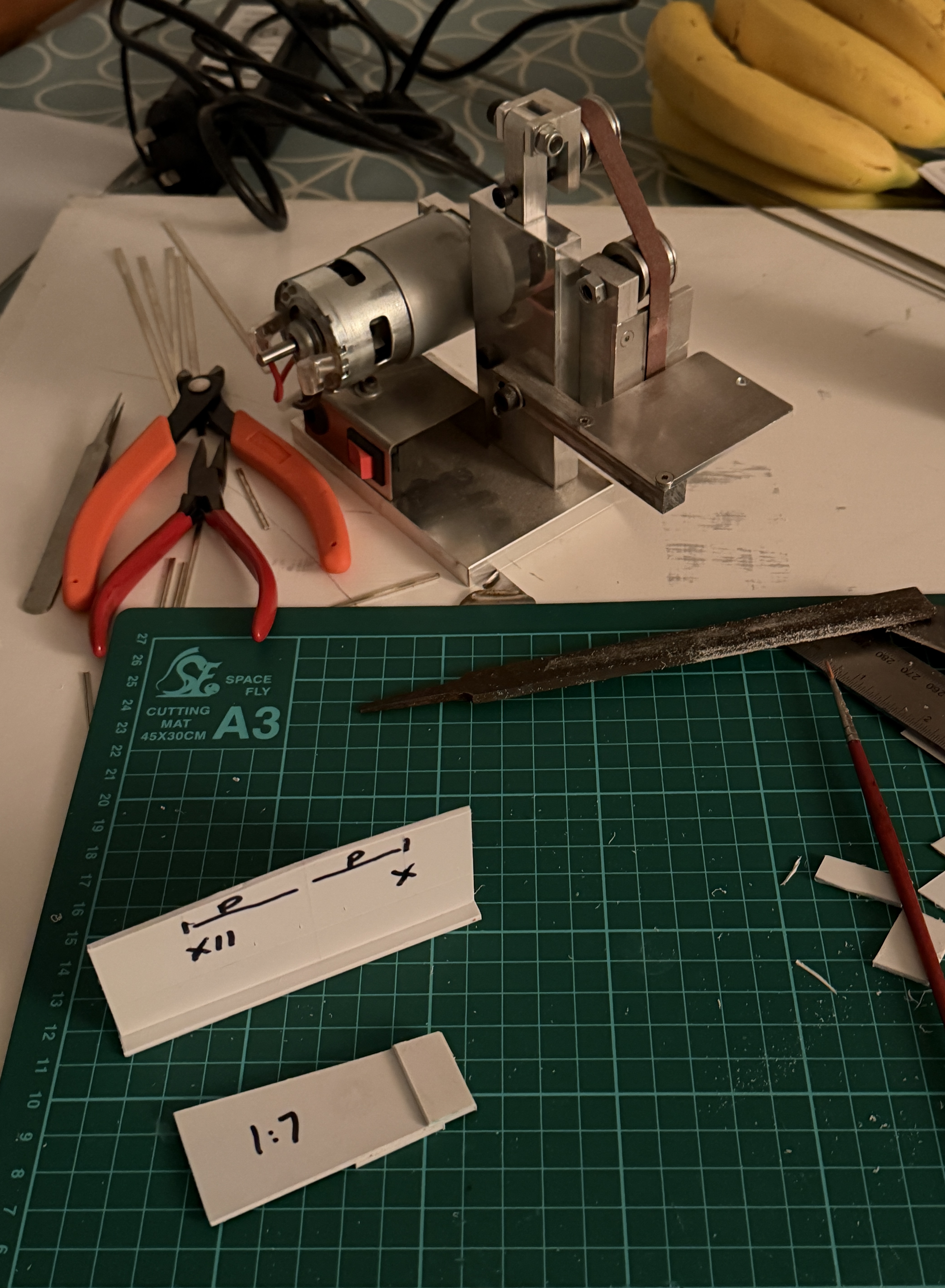
My switches were of 12′ (XII) and 10′ length on the prototype, and I used a 1:7 vee as standard.
The vees were made to follow prototype practice, more or less, by filing the outside of the rail to 1:7 until I had reached the “meat” in the middle of the rail web, then the rail was bent to provide a straight running face, and the other face of the rail then filed away.The photo below shows the main (right) and splice (left rails) after belt sanding, but before tidying up with files prior to assembly.
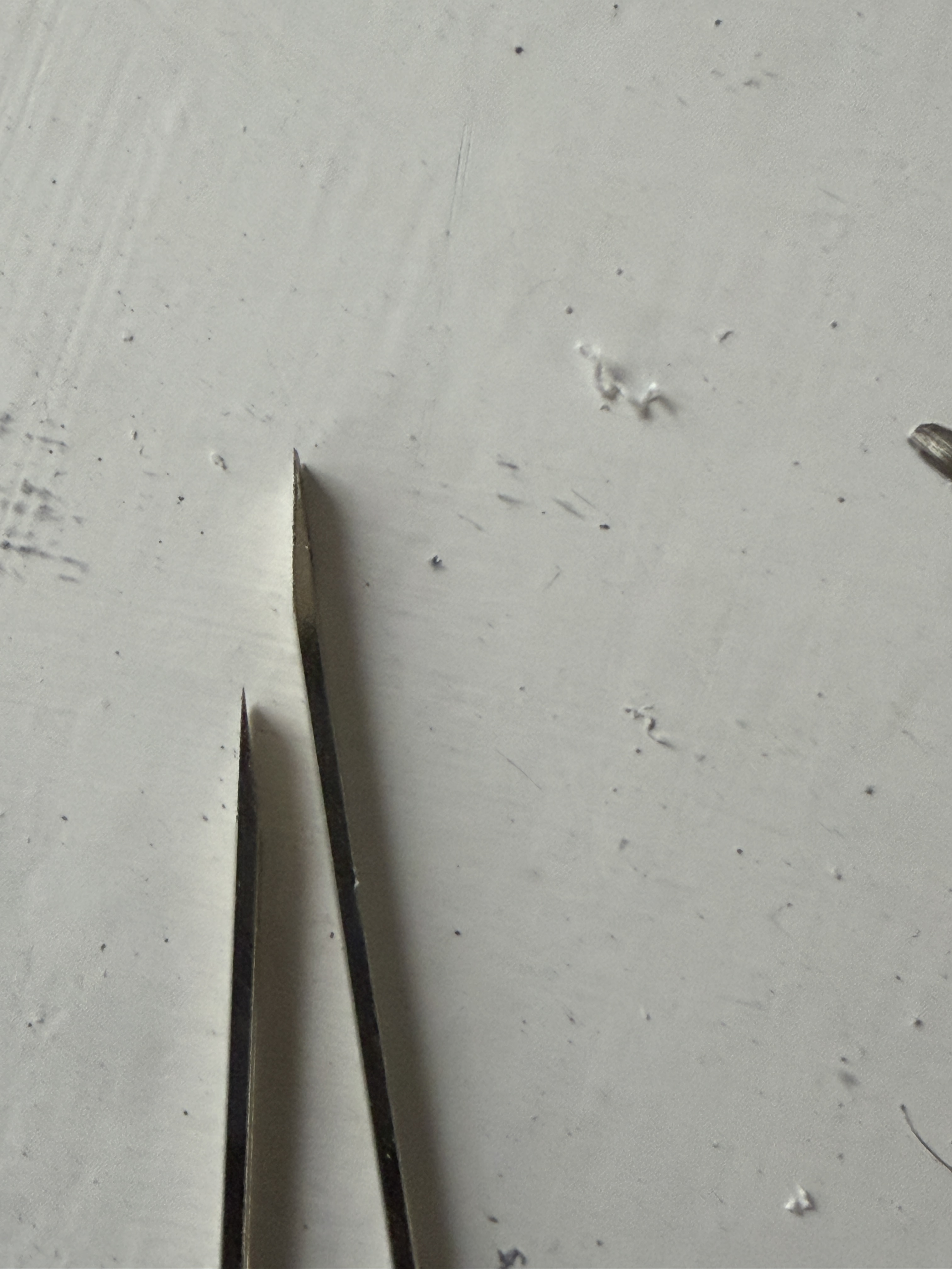
Crossing vees were assembled in a simple wooden jig (because a soldering iron is too hot for styrene!) using higher melting point solder, about 240 degrees.
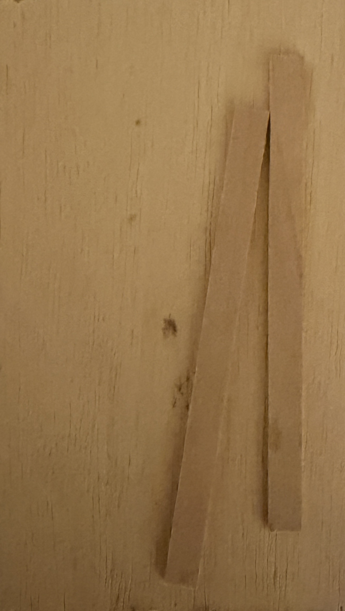
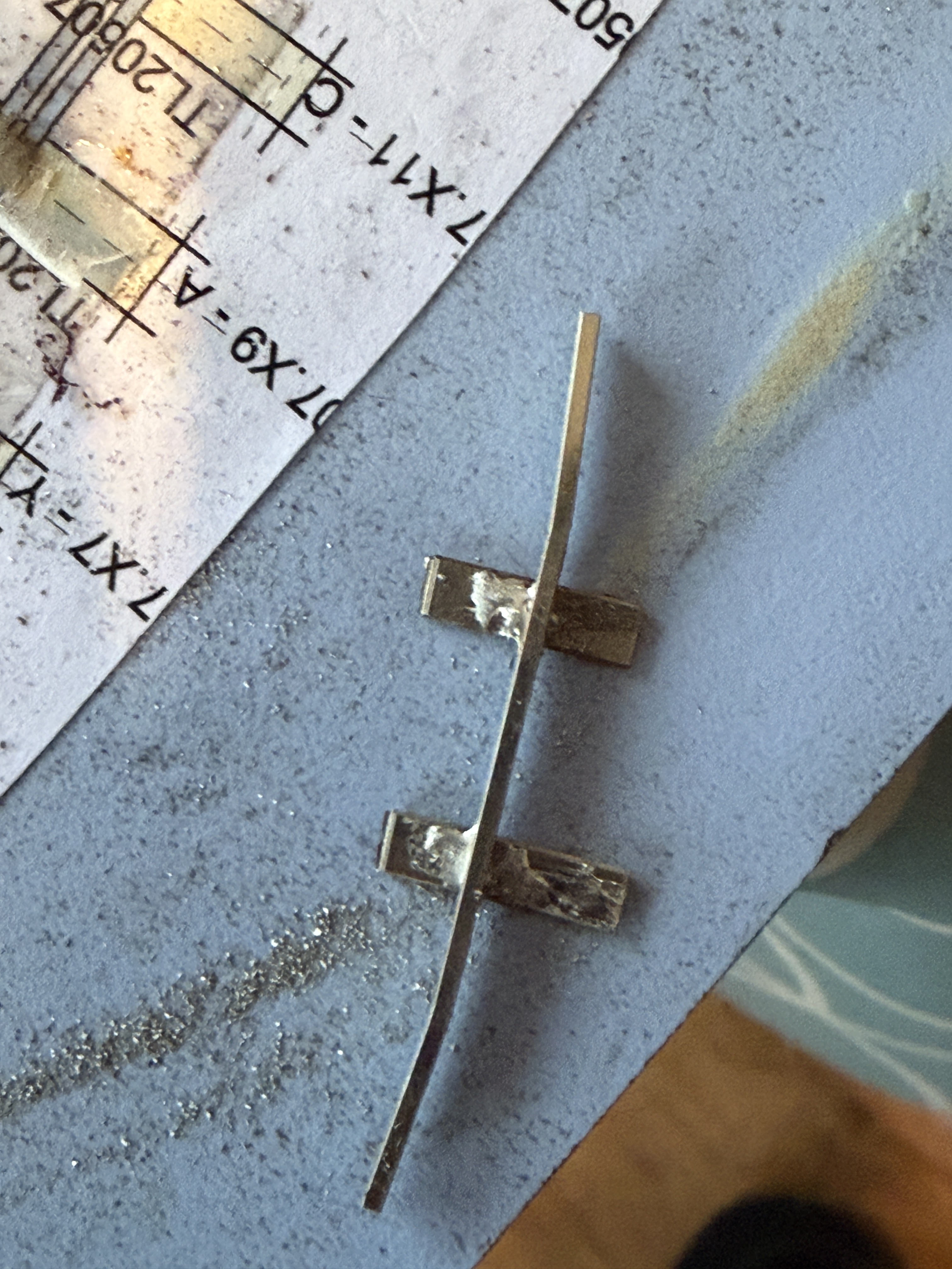
I then cut the wing/closure rails to length, and using pliers, put some small bends in them. At this point I was ready to assemble the crossing vee units. For these, I had purchased some 0.028″ thick nickel silver strip – waste from kit etchings – about 3mm wide, and strips of this were placed our printouts of the crossing vees. To hold all in place, the printout was fixed to a scrap of wood with double sided tape, and the same was used to hold the strips of metal in place.
The crossing vee was carefully put in place and tack soldered to two of the strips, wing/closure rails added one by one. As it happens, I had some aluminium strip of the correct thickness for the flange ways, so a couple of pieces were cut to form an X piece to be laid between the vee and the check/closure rails.
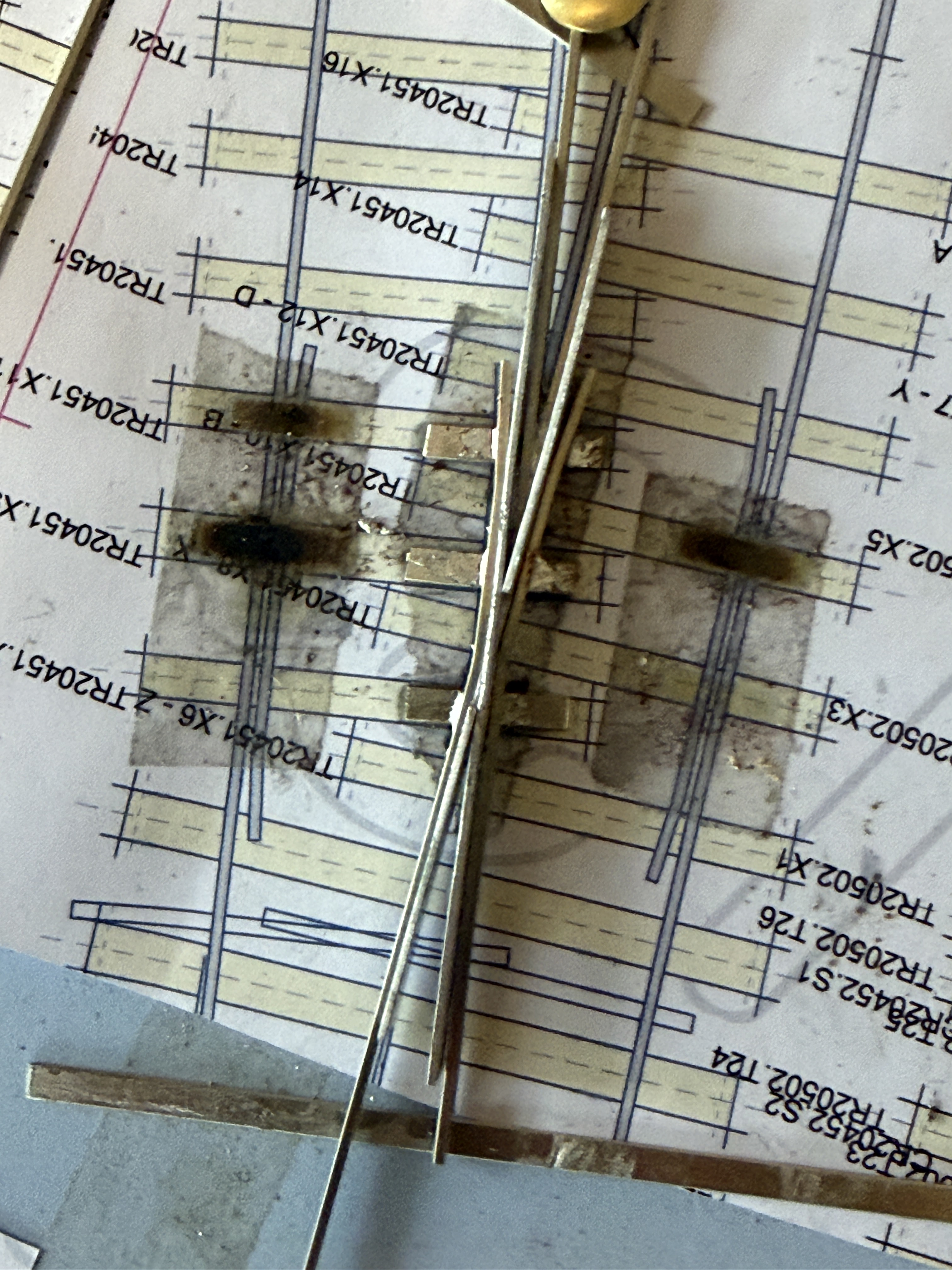
I am not sure how well that has displayed, but hopefully you get the idea.
Needless to say, the double sided tape became quite fluid under the heat, so I couldn’t linger for too long! Also, most of these went together quite easily and quickly, but the last one took more time than the rest all together – I should have taken a break, I think.
But eventually, I had the following collection of crossing vees ready for use – the closure rails and indeed the tail end of the vees were purposely left overlong, for later trimming.
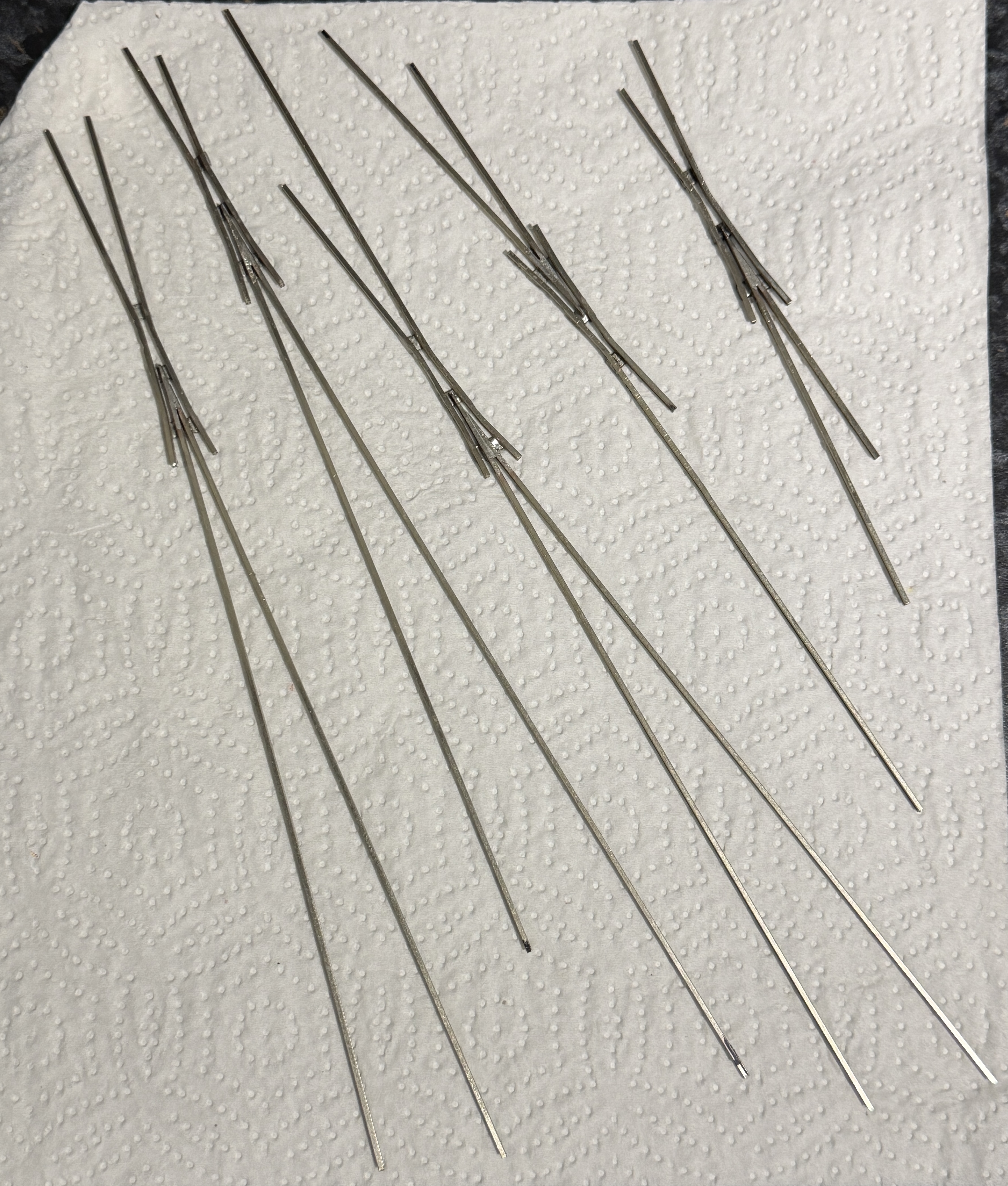
Why the paper towel? Because I had just finished scrubbing these clean of flux, etc, with scouring cream and an old tooth brush, before thouroughly rinsing them. Note also that I have trimmed the nickel silver strips to length, to allow “half chairs” to be fitted later.
I also bent up the check rails. I thought it might be useful to have short nickel silver strips here, too, but in actual fact, that turned out to be unnecessarily fiddly, and they also came off too easily.
Three (-bolt) chairs!
And finally, the chairs. Again, these are SSMRS chairs designed for the code 87 chairs. They come 10 to a spru: one of which is a slide chair. So, out came three small plastic boxes (for LH, RH, and slide chairs) and some spru cutters, and more time in front of the box clipping away. I will explain the LH and RH business in a subsequent post.
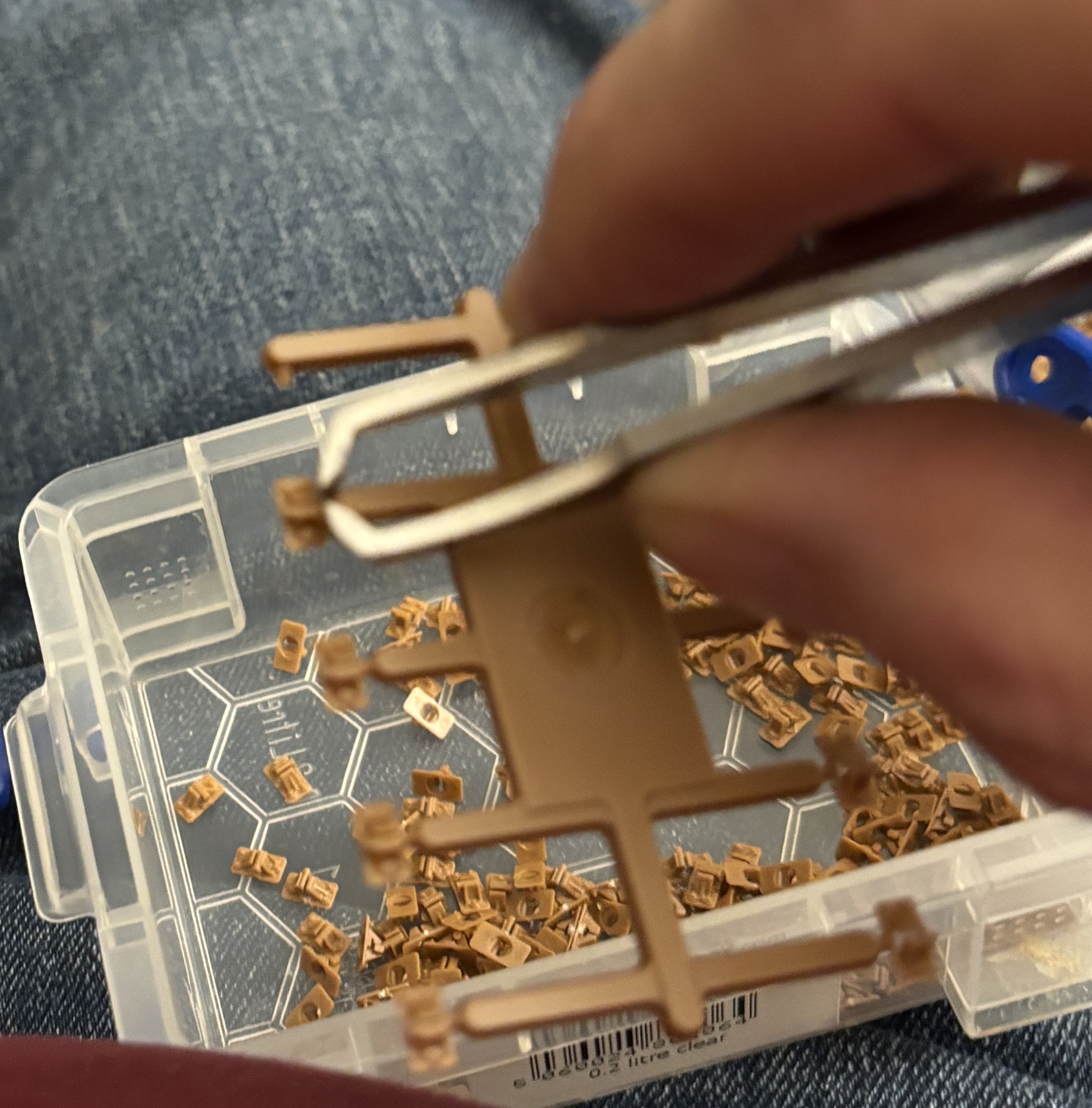
That part was a little tedious – and I needed over 2,000 chairs, so it took a little time…

