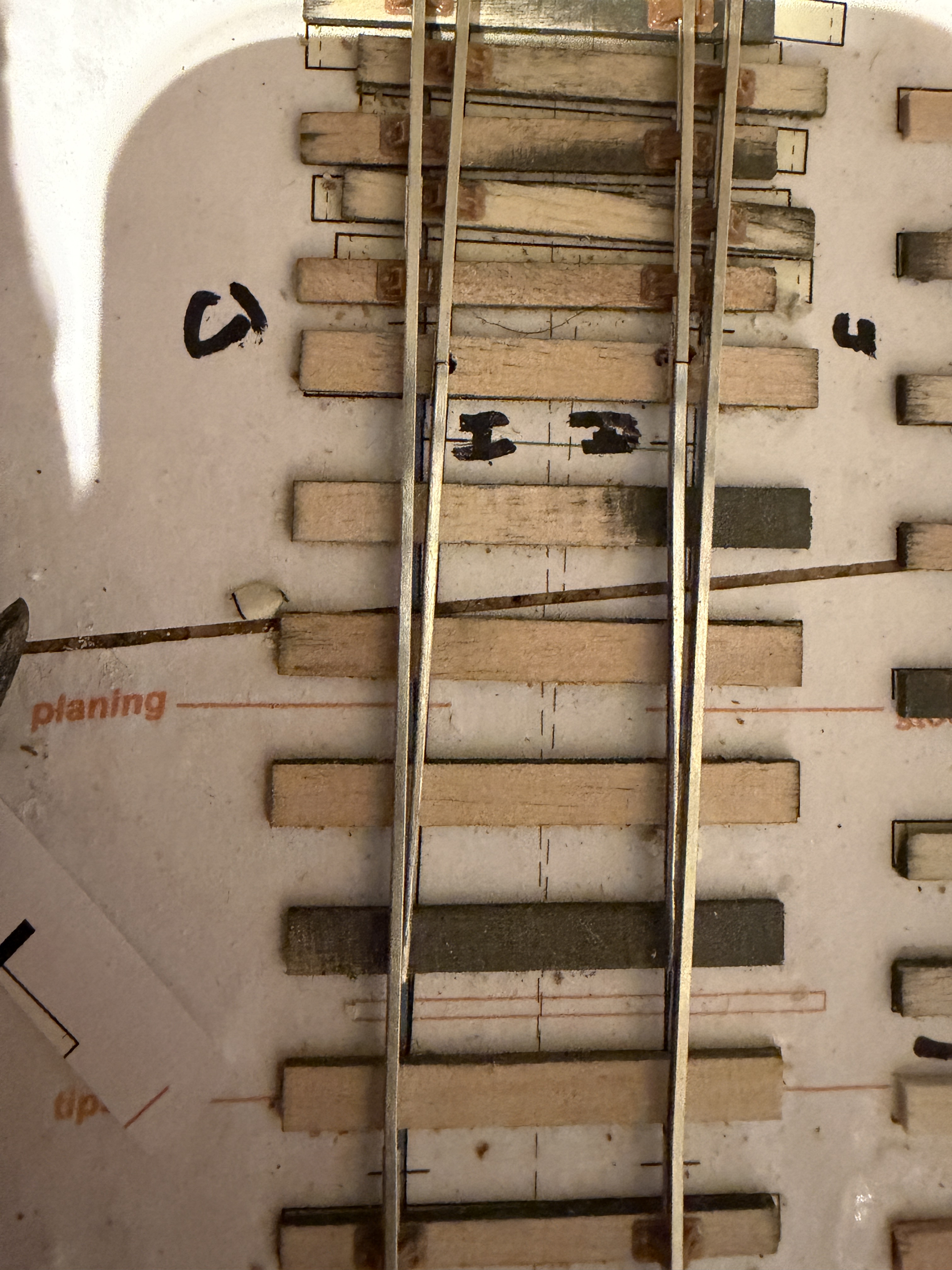
Not sure what sort of web searches I will appear in with that as a title!
In the previous post, I mentioned preparing the rails, filing and assembling the crossing vees and also the wing- and check- rails. I omitted to mention how I filed the switches, so that has become this month’s update!
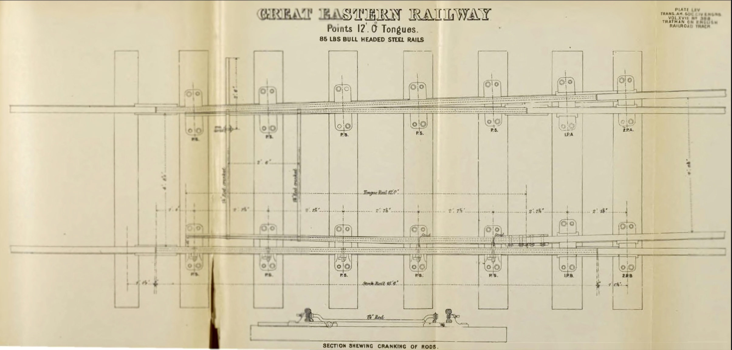
I wanted to try, as much as my limited understanding, skills and tools allow, to replicate “straight cut” switches which are pivoted rather than sprung – i.e. which do not rely on “bending the iron” as our North American cousins sometimes call it – which is what most railway modellers use when making their own track. In my youth, the train set track and indeed code 100 Peco Streamline actually had point blades which were pivoted, but frequently this also involved a crude stamping of metal. My understanding is that on the prototype there was just enough play in the fishplates that joined the point rail to the closure rail to permit the small amount of movement required at the tip of the blades. However, curved and semi-curved switches produce a smoother ride and probably less damage to stock (and the track), but they are largely a “grouping era” introduction, becoming more common on mainlines very quickly, but taking decades in some instances to be replaced on seldom used sidings.
Getting the shape of the blades right (enough) involved filing in four planes, essentially. Now, it is possible to set up a small vertical mill to do the bulk of this, allowing for filing as a finishing job, and it probably saves time if you know how to go about this, but when I read an article on doing this, I got confused so I used a small sanding belt machine instead. This was obviously slightly less accurate, but I didn’t want many blades. Were I building a bigger layout, then it would have been worth setting up a small mill (if you have a Unimat SL or 3, that would be big enough) to do each step in order – remembering that the bull head rail has a top with a bigger head, and that a turnout requires a left and a right switch for each set of points on a turnout.
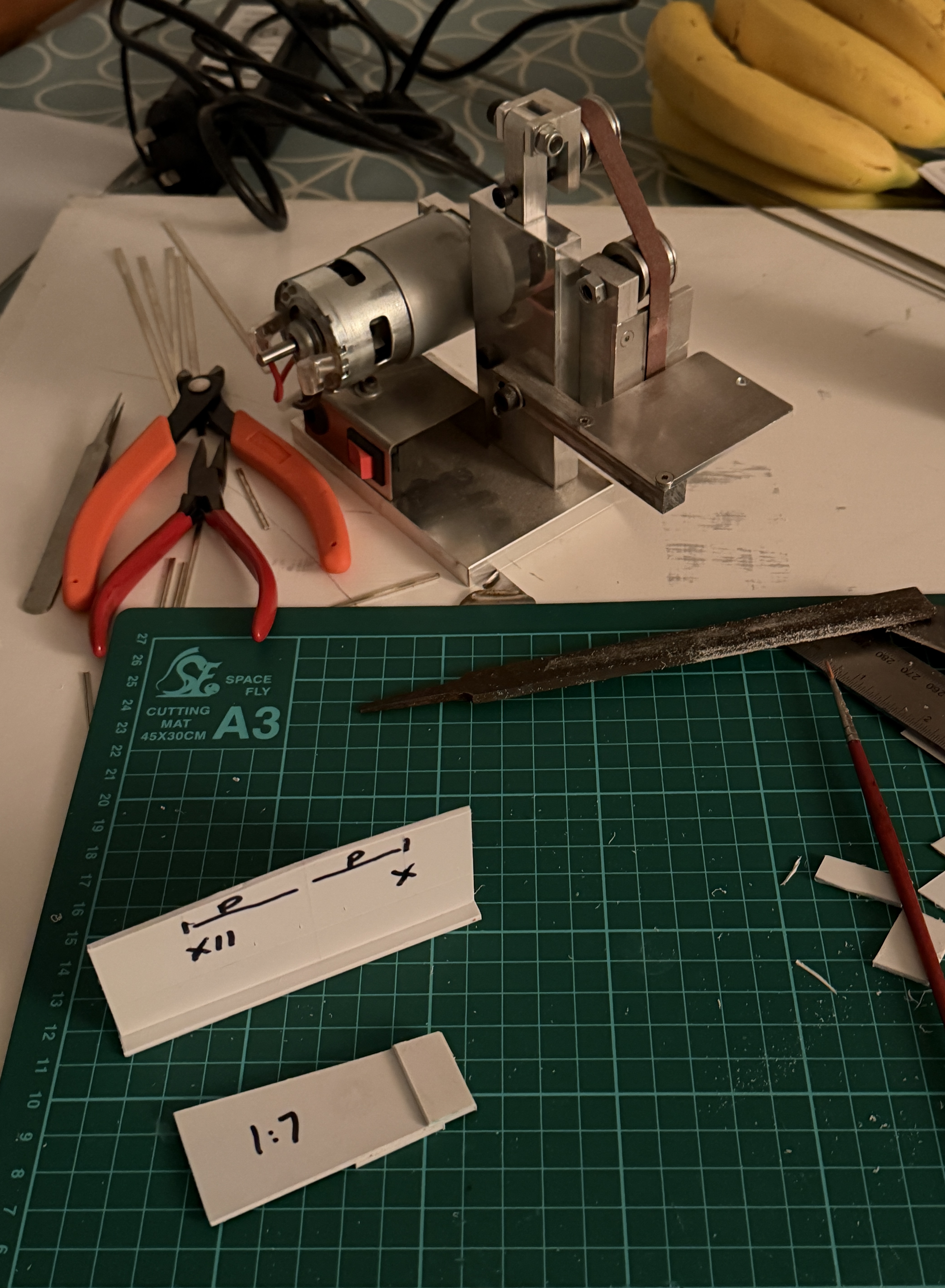
The first move was to file the inner or running face of the blade to a taper, matched against the dimension required for the prototype: I marked this on a simple gauge for the 10′ and 12′ switches I was going to install. This filing process needs to be even, and to reduce the metal at the tip so that the head and foot of the rail are as one with the web of the rail, and also for a short length close to the tip. With a pair of flat nosed pliers, the rail is then gripped at it’s full width (where the filing/planing starts) and the filed section of rail bent slightly to present a straight running rail face. Everything after this is done in reference to that face. This is the first operation and probably worth doing all of the blades in a single session. In an ideal world, I would have also left the foot on the rail, on the running face side. I have done this before, but overlooked it this time!
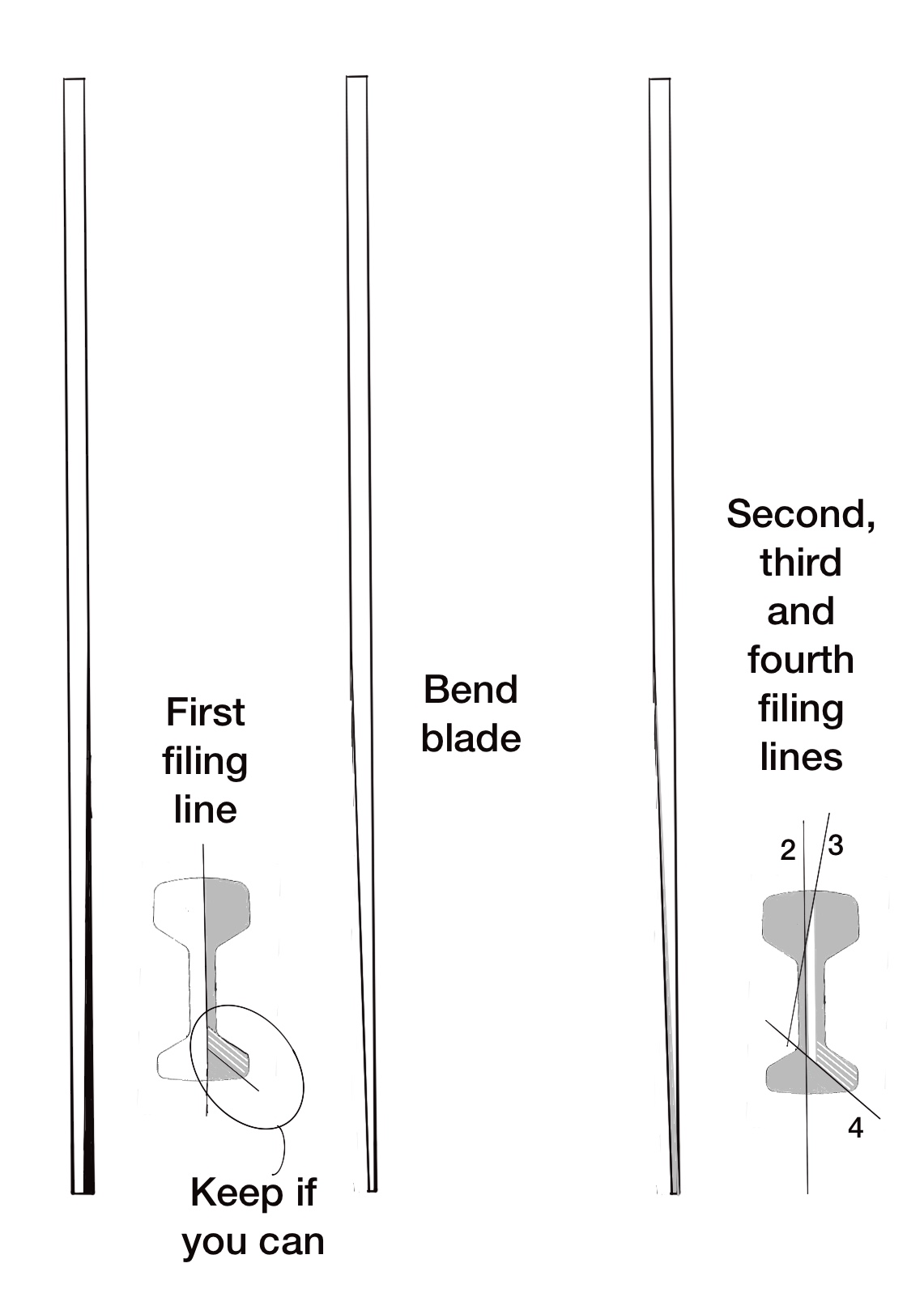
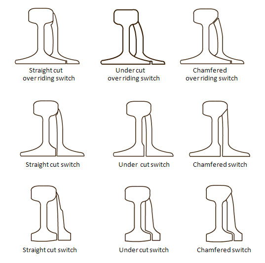
On the prototype, they are working with larger pieces of rail (obviously!) and machine away with some purposely designed milling cutters to get the switch rails to bed into the stock rails, and I wished to get as close to this as I could. This will involve filing/sanding/milling/planing in three slightly different angles. The first operation was the simplest: to file the main body of the rail to an even taper, as had already been performed on the running face. This needs to come to a fairly narrow end, just a “few thou” to leave some meat on the blade. (Were I producing semi-curved or curved sprung switches, I would be filing this to a sharp point, sufficient to draw blood if stabbed into a finger end.) We now have our basic shape ready. The next step is to file (etc.) away the top and the bottom at an angle so that the blade is able to sit into the adjacent stock rail snugly when closed against it. I am sure there must be a proper angle for this, but I more or less did it by eye.

Final finishing off involves cleaning up the work with second-cut needle files, then the leading surface of the blades needs to be filed down slightly to provide a gradual blending in of the blade against the stock rail, and the top of the tip rounding over for the final result.
It is only at this stage of making the blades that I cut them to their final length!
One extra point to note, before the next update, is that the “main” stock rail (usually the straight route) will be provided with a small joggle, and the “turnout” (diverging) stock rail will have a small set in it, just before the switch blade tip. On the real thing, the turnout stock rail would also be straight rather than curved after this set, until the end of the switch is reached. That needs to be remembered when it comes to laying the track.